

Design Guides
SLS(Selective Laser Sintering) is a powdered based fusion technology which requires a laser beam to sinter polymer powder, building parts layer by layer. Powder located in the overflow bin is heated at high temperatures, where a recoating blade deposits an extremely thin layer of the powdered material (0.1 mm) onto the build platform. The building platform then scans an entire cross-section which moves the platform down one layer thickness in height. Powder that has been unsintered will stay in the same spot to support subsequent layers getting rid of the need for support structures. The recoating blade adds another layer of powder on top of the layer that has already been scanned. The laser beam then sinters the cross-section part onto the previously solidified cross-section. This operation is repeated until parts a fully completed. SLS is necessary for users who are looking for a solution in producing functional products with complex geometries This technology has little to no restrictions compared to other 3D printing technologies.Through following these Selective Laser Sintering (SLS) 3D printing design guidelines your parts should come out as intended, but for additional questions and complex problems be sure to reach out to a member of our engineering team.
SLS Design Guides
Tolerances: ± 0.2mm is standard.
Pins: Standard tolerance is +/- 0.3mm so any features with dimensions below this are unlikely to be printed without issue. So pins should be designed ≥ 0.8mm.
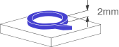
Walls: hicker walls are at risk of warpage. Thin walls can also be a problem area. 0.7mm minimum, but 1mm is preferred.
Slots: Effected by depth or thickness of the wall, ≥ 0.5mm is minimum but will fail toprint if the depth or wall thickness is over 2mm.
Holes: The deeper the hole the larger the diameter needed. All holes should be ≥ 1mm.Blind holes should be designed with an escape hole to remove powder.
Mating (axels, gears): > 0.5mm and < 1mm gaps prevent fusion.Min Clearance: > 0.5mmMax Clearance: > 1.0mm
Text: Sans serif such as Arial with a minimum font height of 2mm.Embossed text: > 1mm high.