

Design Guides
Multi Jet Fusion uses a fine-grained materials that allows for ultra-thin layers of 80 microns. This leads to parts with high density and low porosity , compared to parts produced with Laser Sintering. It also leads to an exceptionally smooth surface straight out of the printer, and functional parts need minimal post-production finishing. That means short lead times, ideal for functional prototypes and small series of end-parts
MJF Design Guides
Tolerances: Layer thickness is 0.1 – 0.2mm. SLA is very accurate in the x and y direc-tions, meaning models are very accurate to CAD. General tolerance is±0.3mm.
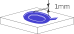
Walls: QSYrapid recommend a wall thickness of at least 1 mm. Large parts may requirelarger wall thicknesses or added ribs or fillets for reinforcement.
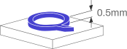
Mating Parts: Minimum 0.5mm gap between axel and bore or other moving parts.
Hollowing: We recommend a minimum of 0.5mm but the larger the better especially as wall thickness or depth increases.
Lattice Structures: Are at risk of closing up if not designed with 0.5mm > minimum height.
undefined
Embossed and Engraved Details: Pins ≥ 0.8mm but even then risk breaking. Embossed features ≥ 0.3mm.